Test Bench Example A Verilog testbench is a simulation environment used to verify the functionality and correctness of a digital design described in the Verilog hardware description language HDL The purpose of a testbench is to provide a way to simulate the behavior of the design under various conditions inputs and scenarios before actually fabricating the
Q out q 3 Generate Clock and Reset The next thing we do when writing a VHDL testbench is generate a clock and a reset signal We use the after statement to generate the signal concurrently in both instances We generate the clock by scheduling an inversion every 1 ns giving a clock frequency of 1GHz Let s consider a simple example of a DUT that adds two 8 bit numbers The Verilog code for the DUT is as follows module adder input 7 0 a b output 7 0 sum assign sum a b endmodule To write a testbench for this DUT we need to create a new module that instantiates the DUT and applies input signals to it
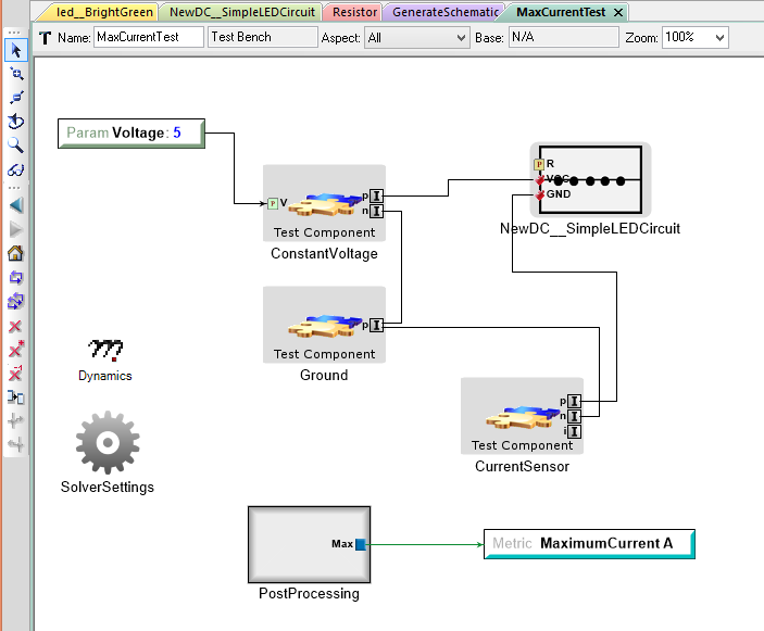
Test Bench Example

Test Bench Example
http://docs.metamorphsoftware.com/doc/_images/01-04-example-test-bench.png

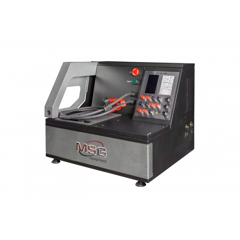
MS004 COM Test Bench For 12V 24V Alternators And Starters For Sale
https://servicems.eu/3431-thickbox_default/test-bench-msg-ms004-com.jpg

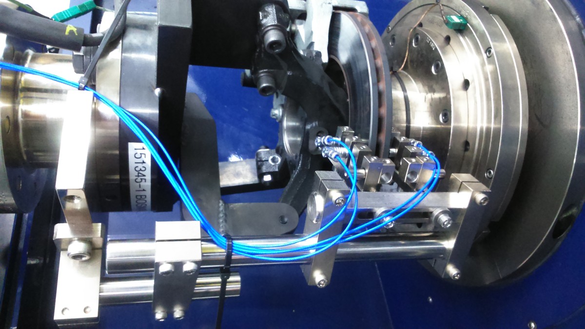
Testing Braking Systems On A Dynamometer Stand test Bench
https://www.bosmal.eu/userfiles/opisy/1491318928186.jpg
SystemVerilog Testbench Example 1 In a previous article concepts and components of a simple testbench was discussed Let us look at a practical SystemVerilog testbench example with all those verification components and how concepts in SystemVerilog has been used to create a reusable environment The first step in creating a Verilog test bench is to write the code The test bench code is separate from the DUT code and serves as the environment in which the DUT will be tested It includes the stimulus generation modules result checking modules and any other necessary components To begin we need to define the input and output signals
Verilog Test Bench Examples The following is an example to a Verilog code Testbench to implement the following function in hardware Verilog Code Verilog Testbench In the Verilog testbench all the inputs become reg and output a wire The Testbench simply instantiates the design under test DUT As a result Verilog starts to look more like a programming or scripting language for testbenches We finally end our testbench with the usual initial block that tells the simulation to run and store the value changes in a particular vcd file Copy Code initial begin Create simulation output file
More picture related to Test Bench Example

ELT3010 Xilinx Test Bench Example YouTube
https://i.ytimg.com/vi/8NF2mRyJO1w/maxresdefault.jpg

VHDL BASIC Tutorial TESTBENCH YouTube
https://i.ytimg.com/vi/B7dDDiCYqTE/maxresdefault.jpg

How To Write Test Benches In Vhdl
https://www.embeddedrelated.com/blogimages/gbreniman/acqeng_list.gif
The simulation process involves compiling the VHDL files and running the simulation The following is an example of a simulation process using ModelSim Launch ModelSim and create a new project Add the VHDL files for the DUT and the testbench to the project Compile the VHDL files by clicking on the Compile button The testbench is also an HDL code We write testbenches to inject input sequences to input ports and read values from output ports of the module The module or electronic circuit we are testing is called a DUT or a Device Under Test Testing of a DUT is very similar to the physical lab testing of digital chips
It begins its execution at the start of the simulation at time t 0 The stimulus is written into the initial block Here s how we write stimulus for and gate in the initial block initial begin A 0 B 0 starts execution at t 0 10 A 0 B 1 execution at t 10 time units Steps involved in writing a Verilog testbench i Declare a testbench as a module module testbench name Example module mux tb ii Declare set signals that have to be driven to the DUT The signals which are connected to the input of the design can be termed as driving signals whereas the signals which are connected to the output

Xilinx Test Bench Tutorial
https://i.ytimg.com/vi/HEbb17SXMJE/maxresdefault.jpg

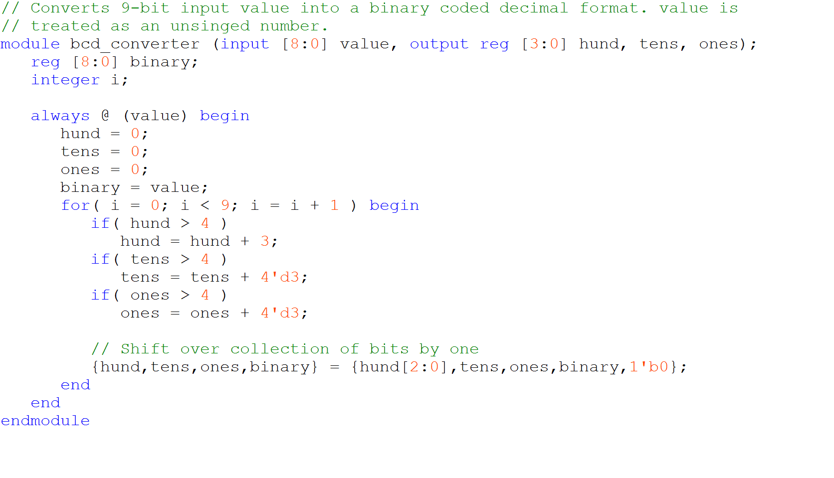
Solved Converts 9 bit Input Value Into A Binary Coded Chegg
https://d2vlcm61l7u1fs.cloudfront.net/media/131/131be89b-7ade-4dd3-978f-15638f1e05a4/php1h4yS6.png
Test Bench Example - As a result Verilog starts to look more like a programming or scripting language for testbenches We finally end our testbench with the usual initial block that tells the simulation to run and store the value changes in a particular vcd file Copy Code initial begin Create simulation output file